GSM INTERFACING WITH ARDUINO
GSM/GPRS module is used to establish communication between a computer and a GSM/GPRS system. This project/ tutorial demonstrates the interfacing of SIM900A GSM Module with Arduino.
Synopsis

GSM/GPRS module is used to establish communication between a computer and a GSM/GPRS system. Global System for Mobile communication (GSM) is an architecture used for mobile communication in most of the countries. Global Packet Radio Service (GPRS) is an extension of GSM that enables higher data transmission rate. GSM/GPRS module consists of a GSM/GPRS modem assembled together with power supply circuit and communication interfaces (like RS-232, USB, etc) for computer. The MODEM is the soul of such modules.

Wireless MODEMs are the MODEM devices that generate, transmit or decode data from a cellular network, for establishing communication between the cellular network and the computer. These are manufactured for specific cellular network (GSM/UMTS/CDMA) or specific cellular data standard (GSM/UMTS/GPRS/EDGE/HSDPA) or technology (GPS/SIM). Wireless MODEMs like other MODEM devices use serial communication to interface with and need Hayes compatible AT commands for communication with the computer (any microprocessor or microcontroller system).

This project/ tutorial demonstrates the interfacing of SIM900A GSM Module with Arduino.

Description

GSM/GPRS MODEM is a class of wireless MODEM devices that are designed for communication of a computer with the GSM and GPRS network. It requires a SIM (Subscriber Identity Module) card just like mobile phones to activate communication with the network. Also they have IMEI (International Mobile Equipment Identity) number similar to mobile phones for their identification.

A GSM/GPRS MODEM can perform the following operations:

1. Receive, send or delete SMS messages in a SIM.

2. Read, add, search phonebook entries of the SIM.

3. Make, Receive, or reject a voice call.

The MODEM needs AT commands, for interacting with processor or controller, which are communicated through serial communication. These commands are sent by the controller/processor. The MODEM sends back a result after it receives a command. Different AT commands supported by the MODEM can be sent by the processor/controller/computer to interact with the GSM and GPRS cellular network.

GSM/GPRS Module

A GSM/GPRS module assembles a GSM/GPRS modem with standard communication interfaces like RS-232 (Serial Port), USB etc., so that it can be easily interfaced with a computer or a microprocessor / microcontroller based system. The power supply circuit is also built in the module that can be activated by using a suitable adaptor.

To interface GSM module with Arduino three connections have to be made between them along with separate power supply.

The three connections are:

1. Connect TX pin of SIM900 GSM/GPRS module to TX pin of Arduino,

2. Connect RX pin of SIM900 GSM/GPRS module to RX pin of Arduino,

3. Connect GND pin of SIM900 GSM/GPRS module to GND pin of Arduino

*Note that GSM board should be powered with separate power source because current from the Arduino will not be enough to drive the GSM Module.

GSM Interfacing with Arduino
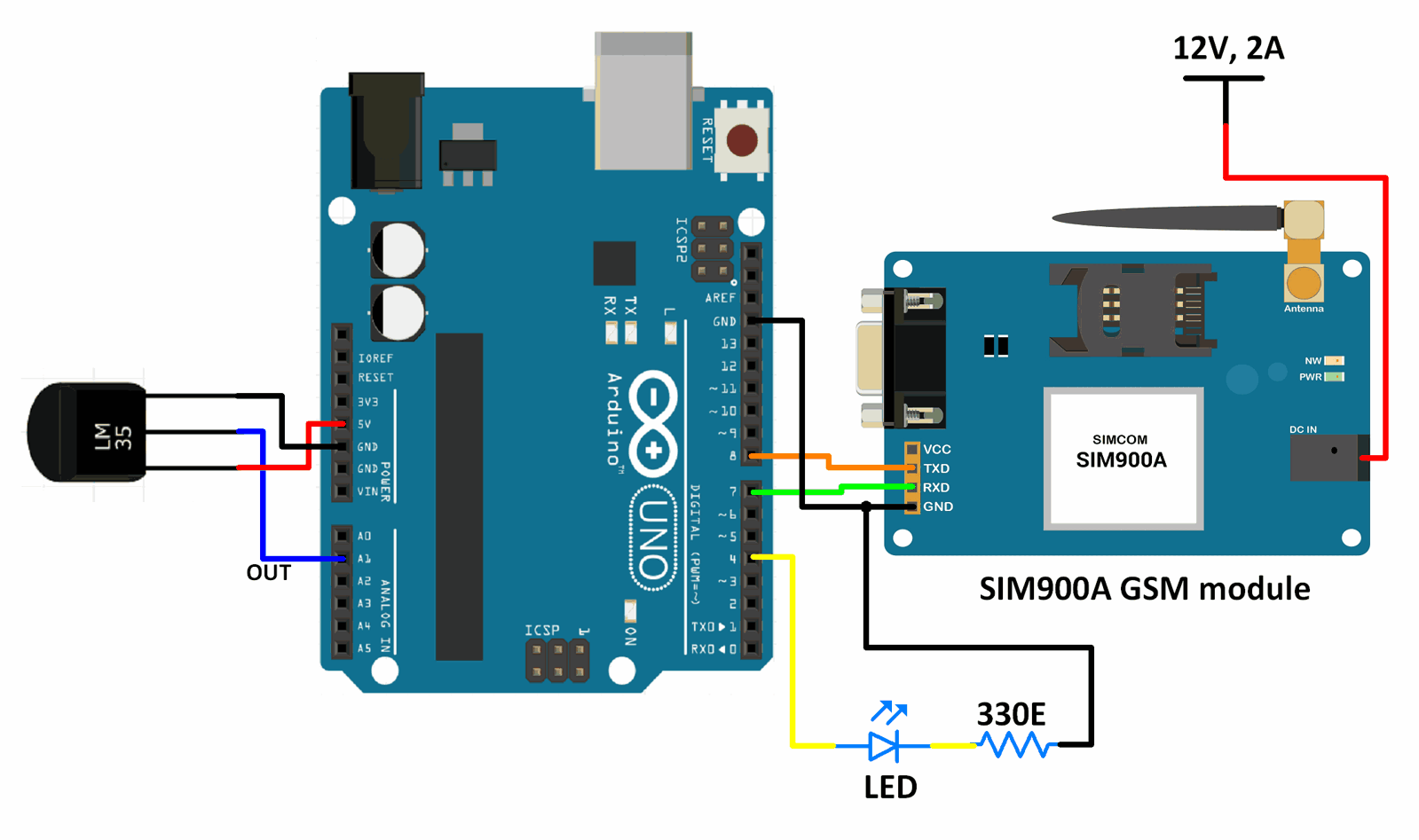

1) Insert SIM card

Open the SIM cardholder by sliding it as per the arrow mark and lift up. Insert the SIM card , so as to align the chamfered corner suits in card holder. After inserting the SIM card, lock the holder by sliding it to the opposite direction of arrow mark.

2) Connect The Antenna

Fix the Supplied RF antenna to the SMA Antennae connector and tighten it by Rotating the Nut ( Never rotate the antennae for tightening ).

3) Connect the Pins

Connect the GSM modem as per the circuit diagram provided

4) Power the Modem

Power the modem from suitable power supply, which is having enough current capacity (>1A).

5) Check the Status of the LEDs

PWR LED - Red LED will lit immediately

STS LED - Green LED will lit after 1-2 seconds

NET LED -Blue LED will starts to blink in fast for few seconds(Searching For Network) and becomes slow blinking once the Modem registers with the Network.

6) Network LED

The Network LED indicates the various status of GSM module eg. Power on, Network registration & GPRS connectivity. When the modem is powered up, the status LED will blink every second. After the Modem registers in the network (takes between 10-60 seconds), LED will blink in step of 3 seconds. At this stage you can start using Modem for your application.

7) Baud rate

The Baud rate supported by the modem is between 9600 and 115200. Make sure the host system is set to the supported baud rate.

NOTE

*The modem automatically sets to the baud rate of the first command sent by the host system after it is powered up. User must first send “A” to synchronize the baud rate. It is recommended to wait 2 to 3 seconds before sending “AT” character. After receiving the “OK” response, Your Device and GSM Modem are correctly synchronized. So there is no need for setting the baud rate using commands.

*Before You Start using the modem, please make sure that the SIM card you inserted support the needed features and there is enough balance in SIM.!!!

Functions Used

1. Sim900_test.readSMS(messageIndex, message, MESSAGE_LENGTH, phone, datetime)

>> This function is used to read the message that is present at the location specified by messageIndex.

>> MESSAGE_LENGTH is the size of the message that is to be read.

>> Phone is a character array in which the phone number of the sender of the message is extracted.

>> Datetime is a character array in which the date and time when the message was received is extracted.

2. GPRS Sim900_test(PIN_TX,PIN_RX,BAUDRATE)

>> This is used to create an object named Sim900_test (can have any other valid name according to user) of the class GPRS.

>> It also defines the pins on Arduino board that are connected to the Rx and Tx pins of the Sim900A module. It also defines the baud rate used for communicating between the board an module.

>> It also defines the pins on Arduino board that are connected to the Rx and Tx pins of the Sim900A module. It also defines the baud rate used for communicating between the board an module.

Error message here!

Show Error message here!


Forgot your password?

Error message here!

Send OTP

Error message here!

Show Error message here!


Lost your password? Please enter your email address. You will receive a password you Need.

Send Error message here!


Back to log-in

Close